Introduction
With the phasing out of game, serial and parallel ports from modern computers and the ever increasing popularity of USB, it makes sense that hobbyists start getting to grips working with USB. Unfortunately, USB is not a simple protocol and can be daunting to implement. Luckily, there are several solutions on the market that can make implementing a USB device much easier.
This project focuses on the use of a USB PIC and the mikroC compiler to convert an old game port joystick to utilize USB. One of the advantages of the mikroC compiler are the built USB HID libraries that make creating a USB HID device a doddle. When writing USB code using the mikroC compiler, the USB device produced is a generic HID device that can be used to transfer data to and from the PIC. However, it is possible to modify the USB descriptor generated by mikroC so that it produces a specific USB HID device, like a keyboard, mouse, joystick or graphics tablet.
Compiler
This project uses the mikroC v8 compiler. However, the methods used will most probably be relevant to other compilers that can generate HID code.
Joystick
The joystick I used for this project is an old IBM 76H1571, photographed below:

The 76H1571 is a 4-button joystick with a throttle and POV hat. What’s interesting to note is that you can’t use the throttle and POV hat at the same time – you can only use one or neither. The two slide switches on the front of the joystick are used to switch the throttle and POV hat on and off, so that you could choose which one you wanted to use.

Because there is no point for this restriction with USB, the converted joystick will be able to use both the throttle and POV hat at the same time. This then makes the two switches at the front redundant, so why not add those as two extra buttons?
In summary, the converted joystick will have the following specifications:
- 2-axis joystick
- Throttle
- 4 direction POV hat
- 6 buttons
HID Report Descriptor
When the compiler generates the USB HID code, it creates a descriptor that is sent to the USB host that tells it what type of USB device it is. A HID device descriptor is slightly different as it has an extra descriptor embedded in it that specifies the type of HID device and how it is used. It is this section that will be modified to change our device into a joystick.
Creating the Descriptor
The USB IF website contains a useful tool that greatly facilitates the creation of HID report descriptors. It’s called the HID Descriptor Tool and can be downloaded for free from the HID Tools page. Once downloaded, extract the archive and run Dt.exe.
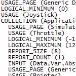
Using the tool, it is possible to create your own report descriptor for your joystick (or any other HID device), specifying the number of axis and buttons it has and any other features (rudder pedals, throttles etc). However, the tool also comes with some premade descriptors that you can immediately use or modify to suit your needs. They are found in the same folder as the executable and are distinguishable by their .hid extension. The premade joystick descriptor is called joystk.hid and this is the one I used. Once loaded, you’ll be presented with the following screen:

I’ve highlighted the important sections in red. From these sections you can deduce the following specs:
- 1 throttle, described by an 8 bit value from -127 to 127
- X and Y axes
- 1 POV hat, taking 4 positions (0-3) and representing the angle 0-270, described by a 4-bit value
- 4 buttons, with each button described by 1 bit
You’ll notice that the REPORT_SIZE property defines the width of the data used to represent the parameter and the REPORT_COUNT property determines how many reports are sent to represent the parameter.
Modifying the Descriptor
Have a look at Modifying the Joystick HID Descriptor to see how.
Adding the Descriptor to your code
With your report descriptor created you need to export it into C code. To do that, click on File->Save As in the HID Descriptor Tool. In the Save dialog that appears, change the file type to Header File (*.h).

This will create a C header file that you can then add into your project.
mikroC Integration
Adding the header file into the descriptor generated by mikroC requires a little bit of work. If you have a look at the mikroC descriptor, you’ll notice that every byte is followed by ‘,0’ (ignoring the quotes, that’s comma zero). You will need to modify the report descriptor you generated to include this padding. After doing that you’ll end up with a descriptor that look something like this:
0x05, 0,
0x01, 0, // USAGE_PAGE (Generic Desktop)
0x15, 0,
0x00, 0, // LOGICAL_MINIMUM (0)
0x09, 0,
0x04, 0, // USAGE (Joystick)
0xa1, 0,
0x01, 0, // COLLECTION (Application)
0x05, 0,
0x02, 0, // USAGE_PAGE (Simulation Controls)
0x09, 0,
0xbb, 0, // USAGE (Throttle)
0x15, 0,
0x81, 0, // LOGICAL_MINIMUM (-127)
0x25, 0,
0x7f, 0, // LOGICAL_MAXIMUM (127)
0x75, 0,
0x08, 0, // REPORT_SIZE (8)
0x95, 0,
0x01, 0, // REPORT_COUNT (1)
0x81, 0,
0x02, 0, // INPUT (Data,Var,Abs)
0x05, 0,
0x01, 0, // USAGE_PAGE (Generic Desktop)
0x09, 0,
0x01, 0, // USAGE (Pointer)
0xa1, 0,
0x00, 0, // COLLECTION (Physical)
0x09, 0,
0x30, 0,
/////////////////////////////////////////
// USAGE (X)
0x09, 0,
0x31, 0, // USAGE (Y)
0x95, 0,
0x02, 0, // REPORT_COUNT (2)
0x81, 0,
0x02, 0, // INPUT (Data,Var,Abs)
0xc0, 0, // END_COLLECTION
0x09, 0,
/////////////////////////////////////////////
0x39, 0, // USAGE (Hat switch)
0x15, 0,
0x00, 0, // LOGICAL_MINIMUM (0)
0x25, 0,
0x03, 0, // LOGICAL_MAXIMUM (3)
0x35, 0,
0x00, 0, // PHYSICAL_MINIMUM (0)
0x46, 0,
0x0e, 0,
0x01, 0, // PHYSICAL_MAXIMUM (270)
0x65, 0,
0x14, 0, // UNIT (Eng Rot:Angular Pos)
0x75, 0,
0x04, 0, // REPORT_SIZE (4)
0x95, 0,
0x01, 0, // REPORT_COUNT (1)
0x81, 0,
0x02, 0, // INPUT (Data,Var,Abs)
0x05, 0,
/////////////////////////////////////
0x09, 0, // USAGE_PAGE (Button)
0x19, 0,
0x01, 0, // USAGE_MINIMUM (Button 1)
0x29, 0,
0x04, 0, // USAGE_MAXIMUM (Button 4)
0x15, 0,
0x00, 0, // LOGICAL_MINIMUM (0)
0x25, 0,
0x01, 0,
// LOGICAL_MAXIMUM (1)
0x75, 0,
0x01, 0, // REPORT_SIZE (1)
0x95, 0,
0x04, 0, // REPORT_COUNT (4)
0x55, 0,
0x00, 0, // UNIT_EXPONENT (0)
0x65, 0,
0x00, 0, // UNIT (None)
0x81, 0,
0x02, 0, // INPUT (Data,Var,Abs)
0xc0, 0 // END_COLLECTION
Now that the descriptor has been padded, the next step is to delete the report descriptor generated by mikroC and replace it with your one. To do that, first create the mikroC descriptor using the mikroC HID tool, then open it up in the editor.
The actual descriptor data itself is stored completely within the DescTables array. The bottom 50 or so lines in the array are the report descriptor (lines 109-160). Delete those lines, and then paste in the new descriptor in its place. Now, the following modifications need to be made to the USBdsc.c file:
- Modify line 23 to correspond to the unpadded size of the report descriptor (i.e. the size of the descriptor generated by the HID tool, without the extra 0’s we need to add for mikroC – 77 bytes in the case of the default joystick descriptor):
unsigned char const HID_ReportDesc_len = 77; - Delete the array bounds for the DescTables array on line 36:
unsigned char const DescTables[] = {
And that’s it. The descriptor should now be correctly mofied to behave as a USB joystick. The easiest way to test this out is to compile the code on to a PIC, plug it into a USB port on your PC and make sure that it is recognized correctly by the PC. Then, go to Control Panel and open up the Game Controllers options dialog. You should be able to see your joystick listed.
 Sending Data to the PC
With the PIC recognized as a USB joystick, the hard part is over. Sending joystick data to the PC is a simple matter. When we created the descriptor earlier, we could work out most of the data format from looking at the descriptor. Some extra experimentation has determined the following specification:
| Value | Range |
| Throttle | -127 (min) to 127 (max) |
| X axis | -127 to 127 |
| Y axis | -127 to 127 |
| POV Hat Up | 0 |
| POV Hat Right | 1 |
| POV Hat Down | 2 |
| POV Hat Left | 3 |
| POV Hat Neutral | 4 |
| Button 1 | 0-1 |
| Button 2 | 0-1 |
| Button 3 | 0-1 |
| Button 4 | 0-1 |
The throttle, X and Y values are all 8-bit values. However, the POV and button values are 4-bits each and so they are packed into one byte. The data format is shown below:
| Bit position | |||||||
| 7 | 6 | 5 | 4 | 3 | 2 | 1 | 0 |
| Throttle | |||||||
| X-axis | |||||||
| Y-axis | |||||||
| Button 4 | Button 3 | Button 2 | Button 1 | POV Hat | |||
With the data format determined, it is a simple matter to write some firmware that interfaces with the some buttons and potentiometers and sends the data to the PC, to confirm that the firmware is working correctly. The behaviour of the PIC joystick can be examined using the Game Controllers options dialog in Control Panel.
Hardware
With the USB firmware tested and running fine, it is time to move on to the actual joystick conversion. The first thing that needs to be done is to open up the joystick and remove the existing circuitry and the gameport cable:

Switch Setup
The next step is to work out how all the switches and potentiometers are wired together. The potentiometers for the joystick axes and throttle will probably be simple to spot and simple to wire as well as all they need is power, ground and a voltage out to the PIC. The switches might prove to be a little tricky, depending on the joystick. By tracing the tracks on the PCB in the stick, it has been determined that the switches are connected according to the following diagram:


The interesting one to note is the POV hat. Instead of being 4 separate switches, the POV hat is wired up as an analogue system, where the resistance across the green and orange wires determines which button was pressed. The following table shows the resistance of each switch:
| Switch Position | Resistance (Ohms) |
| Neutral | 80k |
| Up | 200 |
| Right | 20k |
| Down | 40k |
| Left | 60k |
Therefore, in order to find out the direction of the POV hat, its wires will be connected in a potential divider circuit as shown below:

When wired to a 5V supply, this will give the following voltage outputs:
| Switch Position | Voltage (V) |
| Neutral | 3.9 |
| Up | 0.045 |
| Right | 2.4 |
| Down | 3.2 |
| Left | 3.7 |
Circuit
With the joystick wiring determined, the next step is to design a circuit that can interface with all the buttons and pots and send the data to the PC. My circuit uses a PIC18F2550 running at 20MHz. The switches are all connected to PORTB and the potentiometers and POV hat are connected to the ADCs on PORTA. The schematic is shown below (click on the image to see the full-size version):

The stripboard layout is shown below (note the 3 wire links. Click for larger image):

With the circuit built and tested, it can finally be placed into the joystick base and the gameport cable replaced with a USB one. A photo of the converted joystick is shown below:

And that’s it! Put everything back together again and plug the joystick into a free USB port. With luck, the joystick will be correctly recognized by Windows. You can then calibrate it and start using it to play games that support a joystick.


Conclusion
This project kills two birds with one stone. On one hand, the project shows you how to create a USB HID Joystick device and convert your old joystick into a modern one or even create your own joystick. On the other hand, if you know how to create the firmware for a USB joystick, the steps to create the firmware for any other HID device are very similar and the only difference will be in creating the HID report descriptor and how you send the data to the PC.
Project Downloads
You can download the project files here, including the source code and schematics.
i have a 8MHZ crystal, but i cant figure out how to get mikroC to work with this 8Mhz crystal, i have no 20mhz crystals
do you know how i can set this up?
how did you solved the trouble about the crystal
OK, i sorted it, and YOU RULE! thank you for the code! at least i have something to go with now 🙂
Thanks! Glad you got it sorted.
interesting explantion
but i have one question. i am using
psoc programmer & designer. so do
you think (can it work?) if i program the
PIC18F2550 using psoc prog.
thank you in advance
Jos
I doubt that you could program a Microchip device using a PSoC programmer. You could still build this project using a PSoC if you find some USB HID sample code: the changes to the descriptor will be very similar.
#include “Definit.h”
#include “VARs.h”
Sir i am to submit project very soon so please reply.
i am using mikroc and 18f4550 so what are these files for do they need to be changed in my case.
Definit.h and Vars.h can be found in the Examples directory in your MikroC installation folder. They contain various definitions that the HID Library needs to work. Just copy them to your project folder. You don’t need to edit them.
Hi Amr !
I read your page one hundred time but my project don’t want to work 🙁
What did you want to say by “unpadded size of the report descriptor”?
how can I know it? 🙁
Thanks for times you spend for us
The unpadded size is the number of bytes in the descriptor without the extra 0’s that you need to add in mikroC.
Hey, I was just wondering if you possibly had a larger picture of your circuit board. I’m trying to follow the protoboard diagram, but I’m not sure what the X’s are and it’s kind of confusing me :/
Great guide though, I’ve had one of these sitting around forever!
Hi Matthew,
The X’s on the stripboard layout indicate where you should break the tracks. Regarding a larger circuit diagram, if you click on the image of the schematic you will be taken to a full size version. If that’s not big enough then please get in touch via the Contact page and I’ll send you a larger version.
Glad you like the guide!
Amr
how do I modify the unsigned char const ProductDescr?
I already had changed the name, but it was necessary to change the product id to show the new name.
I used the mikroC’s tool to create the name.
Hi Amr Bekhit,
I was trying to modify your code in to a wheel
with but it doesnt work. i am new to this. The problem is that i don’t understand to change the hid description in mikroC and the connection between the program usbdsc and joystick part. The joystick part is done.
the compiler doesnt have any errors zo the problem is in usbdsc.C. The part of the software DT.exe i understand but what do i need to change than in mikroC. Sorry for my bad english
Regards,
ev
i have found my problem i for got the usbpll in the programmer
Whe I “build” in MikroC Pro I get numerous error!? Why is this please?
Sorry it appears my quote did not post properly?
I will post them again without quotes. My errors upon “builing”—>
0 122 Compilation Started USBJoystick.c
13 396 Invalid declarator expected'(‘ or identifier USBJoystick.c
13 300 Syntax Error: ‘)’ expected, but ‘;’ found USBJoystick.c
14 300 Syntax Error: ‘;’ expected, but ‘bit’ found USBJoystick.c
14 398 Declarator error USBJoystick.c
14 396 Invalid declarator expected'(‘ or identifier USBJoystick.c
14 300 Syntax Error: ‘)’ expected, but ‘;’ found USBJoystick.c
14 402 ; expected, but ‘}’ found USBJoystick.c
15 371 Specifier needed USBJoystick.c
15 396 Invalid declarator expected'(‘ or identifier USBJoystick.c
15 312 Internal error ” USBJoystick.c
0 102 Finished (with errors): 18 Sep 2011, 23:09:14 usbjoystick.mcppi
Oh and sorry to be a pain, but I forgot to mention I am building using a pic18f4550
Many thanks
Regards
Steve
It’s ok,
I solved my own problem 🙂
There’s obviously been a lot of changes to the library since this “tut” was written, and mikroc pro also handles specific bits differently. Now I’m just stuck with the HID desc’. A blank device will display if I use the desc’ made by mikroc (but obviously this is unusable), however if I modify the desc’ I get an exclamation mark next to the device (no joystick symbol) 🙁
OK… That problem was solved. But now when I press a button nothing is actually happening!? I guess the wrong (or none at all) data is getting transmitted?? Gonna have to do some more research, unless anyone has pointers please??
Hi,
I’m a newbie in USB programing.To learn the FUN way,i plan to convert my old joystick to USB joystick.I understand how the Descriptor works.I converted it to use in other compiler (not Mikro C).It works.It connects & shows in Game Controllers but..it didn’t work.It freezes there & nothing happen even when i tried to move the pots.What could went wrong.?Help
hi,
i’m kinda new to these things and i would like to how would i recompile this project source after editing??? i doesn’t hav a MikroC project file
plz help………..
i am not able to understand what to do to program the pic ….. give me more tips? Some errors appear in the compiler …. i need it for may notes at school…
error: 0 360 Unresolved extern ‘USB_Init_Desc’ __Lib_USB_genHID.c
all using miKro compiler c pro 5,61
thanks
It sounds like you haven’t enabled the USB library for your project. You can do so from the library manager.
oh! Now I understood, i have compiled the program without erros! soo…. another problem…. the potenciometer…. you gave a table with the values of resistence… but, the nominal value is??? sorry for the english mistakes…. i am a student of english….
Hi Daniel,
I presume you’re talking about the resistances of the POV hat. The nominal position is called “Neutral” in the table.
thanks, but i trying to know the values of the potenciometers that are in J8, J9….
Ah I see. Those potentiometers were the ones for the X, Y and throttle axes already fitted in the joystick. I didn’t measure what their resistances were, but that doesn’t really matter, as I’m just interested in the voltage on their wipers. I’m sure most potentiometers you can find will work just fine.
Hi! Now I am having some problems with the code, some errors appear when I build the project… I want to modify something in your project… that are working perfectly… but only with your Hex file… not mine.. could you help me….? if you inform your e-mail… it would be easier..
270 123 Compiled Successfully USBdsc.c
0 122 Compilation Started USBJoystick.c
13 305 Inconsistent type USBJoystick.c
13 305 Inconsistent type USBJoystick.c
13 396 Invalid declarator expected'(‘ or identifier USBJoystick.c
22 324 Undeclared identifier ‘HID_InterruptProc’ in expression USBJoystick.c
34 324 Undeclared identifier ‘HID_Enable’ in expression USBJoystick.c
43 316 Identifier expected, but ‘bit’ found USBJoystick.c
43 402 ; expected, but ‘bit’ found USBJoystick.c
45 316 Identifier expected, but ‘bit’ found USBJoystick.c
45 402 ; expected, but ‘bit’ found USBJoystick.c
45 424 ‘}’ expected ‘;’ found USBJoystick.c
91 424 ‘}’ expected ‘}’ found USBJoystick.c
0 102 Finished (with errors): 08 jun 2012, 14:43:04 MyProject.mcppi
hello
i want to replace the analog X-Y with an accelerometer do you think it’s possible in your code like this project
http://www.starlino.com/usb_gamepad.html
thanks
I’d imagine that would be relatively simple to do. All you would need to do is read the accelerometer data for both the x and y axes and transmit those values in place of the joystick’s x and y values.
Can anyone tell me the changes i’ll need to make to this code to make it work 18f4550…i’m fairly new to this…
Hello!
I just trying to adapt Your code for Mikroc for PIC v.5.8.0 and got only hid device in my hardware, but instead of joystick. can You help me to resolve this problem?
Best regards,
Valdis Bogdans.
hello
i try to add bootloader to your code but no luck do you have a idea to keep a bootlader like HID where code need to start at 0x01000
THANKS
I modified the descriptor and I’m able to see the progress bar of the throttle and rudder in the joystck properties Windows, but have no reaction in the flight sim. Instead X and y works. What’s wrong? What I have to add again inot descriptor to see this 2 axis?
Thanks
I use mikroC PRO for PIC cannot open this file.How to open it? thank
I dont understand what to modify in the USBdsc.c file and when I build that c file I get an error, main function not defined although I included Definit.h and VARs.h in the project file. please help me???
ola ficou muito bom o projeto mais eu tentei acresentar mais 4 analogicos no descriptor mais
nao funciona porque ?
hello got very good design more I tried 4 more acresentar Analogue descriptor in more
does not work why?
Pingback: Homemade USB Joystick :: RessJoys 1.0 | Fairybotics
Hi,
there is blue line in the schematic is the line connected with throttle and x,y axis midpoint or connected separately?
The blue line is a bus line. It shows that B0..B5 on connectors J1..J5 are connected individually to B0..B5 on the PIC. Same with A0..A3
Thanks for your response…im glad u r active now…got it…I have one more question I made the schematic in proteus but potentiometers are not working…when I set potentiometer value 0 then throttle bar become half red. here is my dropbox video link for better understanding https://dl.dropboxusercontent.com/u/19334358/joy.mp4
Hi,
I wrote HID descriptor for Joystick, the joystick has 8 axis. I want to know, is this right that Wheel and Dial usage for trim wheel and flap axis. also how do I add 8 buttons into the below code I have many tried for buttons but failed?
0x05, 0x01, // USAGE_PAGE (Generic Desktop)
0x15, 0x00, // LOGICAL_MINIMUM (0)
0x09, 0x04, // USAGE (Joystick)
0xa1, 0x01, // COLLECTION (Application)
0x05, 0x02, // USAGE_PAGE (Simulation Controls)
0x09, 0xbb, // USAGE (Throttle)
0x15, 0x81, // LOGICAL_MINIMUM (-127)
0x25, 0x7f, // LOGICAL_MAXIMUM (127)
0x75, 0x08, // REPORT_SIZE (8)
0x95, 0x01, // REPORT_COUNT (1)
0x81, 0x02, // INPUT (Data,Var,Abs)
0x05, 0x01, // USAGE_PAGE (Generic Desktop)
0x09, 0x01, // USAGE (Pointer)
0xa1, 0x00, // COLLECTION (Physical)
0x09, 0x30, // USAGE (X) for ailerons
0x09, 0x31, // USAGE (Y) for elevator
0x09, 0x32, // USAGE (Z) for rudder
0x09, 0x33, // USAGE (Rx) for spoiler
0x09, 0x34, // USAGE (Ry) for throttle 1
0x09, 0x35, // USAGE (Rz) for throttle 2
0x09, 0x38, // USAGE (Wheel) for trim wheel
0x09, 0x37, // USAGE (Dial) for flap
0x95, 0x08, // REPORT_COUNT (8)
0x81, 0x02, // INPUT (Data,Var,Abs)
0xc0, // END_COLLECTION
0xc0 // END_COLLECTION
Let me correct your mistake. The two sliding switches at the bottom of the IBM 76H1571 flight stick function as follows:
The left switch toggles between the top POV hat and the left-side throttle; it is a selector for one or the other.
The right switch controls whether holding the trigger(Button 1) registers as a continuous press (hold) or as intermittent presses (similar to autofire/turbo).
I arrived at these conclusions by testing in DOS using the command-line program “thrust.com B”.